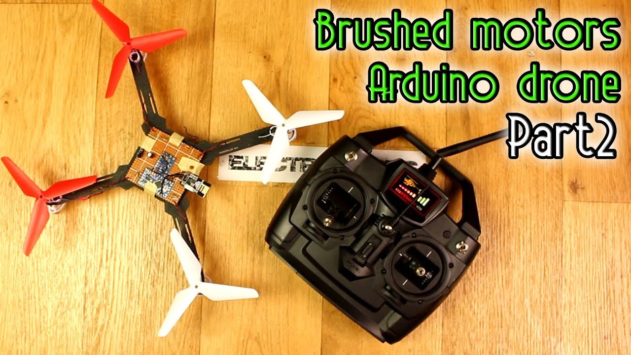
You’re embarking on an exciting journey to build your very own Arduino drone, focusing on creating the flight controller board with some helpful guidance from JLCPCB. This second part of the project series brings you a step closer to mastering the craft as you connect MOSFETs for each motor and dive into the world of MultiWii code to check functionality. Though the skies might still be a little distant due to a minor DC motor hiccup, there’s plenty of learning and experimenting to keep your curiosity ignited.
As you continue, you’ll explore two PCB design options—using a prototyping board or crafting a custom one—all while constructing the drone’s flight controller with tools like the Arduino Pro Mini. This project is all about learning, sharing ideas, and perhaps even preparing to launch a Kickstarter for those looking to dive deeper into the educational side of drone-building. Don’t worry about getting lost along the way; resources, schematics, and a supportive community await to help turn your ambitious project into reality.
Best & Fast Prototype ($2 for 10 PCBs): https://www.jlcpcb.com
Your thanks to JLCPCB for supporting this video.
This is your second video in this project series. Here, you are building the flight controller board. You will connect the MOSFETs for each motor, prepare/upload the MultiWii code, and test if everything is working. Due to a DC motor failure, your drone isn’t flying yet. Stay tuned for future parts.
Support your projects on Patreon: /electronoobs
Your Q&A page: http://electronoobs.com/eng_preguntas…
Channel in Spanish: /electronoobs en español
iforced2D channel: • Data telemetry with MultiWii integrat…
COUPONS FOR YOU
Creality CR10 mini: https://www.gearbest.com/3d-printers-…
COUPON: “CR10MINI”
Anet A8: https://www.gearbest.com/3d-printers-…
COUPON: “A8KIDA”
Creality CR10: https://www.gearbest.com/3d-printers-…
COUPON: “11CR10US” or “11CR10EU”
Tevo Tornado: https://www.gearbest.com/3d-printers-…
COUPON: “Tornados” or “TornadosUS”
PROJECT LINKS
Transmitter video: • Arduino drone – Part2 Transmitter & R…
Tutorial webpage: https://www.electronoobs.com/eng_ardu…
Part list: https://www.electronoobs.com/eng_ardu…
Schematic: https://www.electronoobs.com/eng_ardu…
3D drone body: https://www.electronoobs.com/eng_ardu…
Multiwii code: https://www.electronoobs.com/eng_ardu…
MPU6050 test code: https://www.electronoobs.com/eng_ardu…
NRF24 test code: https://www.electronoobs.com/eng_ardu…
Like share and subscribe to motivate you. Thank you.
Acknowledging Support and Series Overview
Appreciation for JLCPCB’s Sponsorship
Hey there! It’s great to have you back for the second installment of our exciting journey into building an Arduino-based drone with brushed motors. Before we dive into the nitty-gritty of today’s build, we want to extend a heartfelt thank you to JLCPCB for their invaluable sponsorship. Their support has made this project possible by providing us access to high-quality PCB prototypes at really affordable prices. For anyone looking to enhance their electronics projects, JLCPCB is the go-to place for all your PCB needs.
Series Structure and Progression
In this series, we aim to take you from the basics of designing and assembling a drone to deploying it in flight. We began with an introduction to choosing between prototyping drill PCBs and designing custom ones, while also covering SMD component soldering, bootloader burning, and code uploading. With each video, we’re building upon foundational knowledge and moving closer to seeing our drone lift off. In today’s part, we’ll tackle creating the flight controller board, connecting MOSFETs per motor, and preparing the MultiWii code for testing.
Patreon and Community Engagement
Your encouragement on platforms like Patreon drives this project forward, and we’re thrilled by all the support you’ve shown. This project isn’t just a build; it’s a vibrant learning community. We encourage everyone to dive into the comments section, offering insights, asking questions, and sharing experiences. Your feedback fuels our passion and guides the future direction of this series.
PCB Design Options for the Drone Flight Controller
Prototyping Drill PCB
In the previous video, we reviewed the benefits of using a prototyping drill PCB for beginners. This method allows for hands-on experience without the complexities of custom design, making it ideal for hobbyists and learners who are just getting started. The ease and accessibility of prototyping PCBs let you test various configurations, making it a flexible choice for our project.
Custom PCB Design Considerations
While prototyping PCBs are great for learning and experimenting, custom PCBs offer streamlined functionality for more advanced makers. With custom designs, you can optimize the layout for performance and aesthetic appeal. This might include reducing the size, enhancing heat dissipation, or embedding specific components. As our project evolves, we may transition to a custom design to push its boundaries.
Previous Video Recap on PCB Design and Setup
Last time, we explored the initial steps in designing and setting up our PCB, including soldering SMD components and burning the bootloader onto the Arduino. This laid the groundwork for today’s focus, building the flight controller using a prototyping PCB, and integrating an Arduino Pro Mini.
Components and Tools Required
Arduino Pro Mini
The heart of our flight controller is the Arduino Pro Mini—a compact yet powerful microcontroller that fits perfectly into our drone’s lightweight design. Its versatility and ease of programming make it an excellent choice, offering plenty of processing power for our needs.
MOSFETs and Schottky Diodes
To efficiently manage motor control, we’ll be incorporating MOSFETs and Schottky diodes. These components ensure our motors receive the right power and protect against back EMF, which could potentially damage the control circuitry. The integration of these components will allow us to smoothly manipulate motor speed.
MPU 6050 Sensor Integration
For stability and control, integrating an MPU 6050 sensor is crucial. This sensor provides real-time data on the orientation and movement of the drone, communicating with the Arduino to maintain balanced flight. Proper integration is essential for achieving steady and responsive flight dynamics.
Soldering and Component Assembly Tools
To bring everything together, you’ll need some basic soldering tools, including a soldering iron, solder wire, and maybe a helping hand tool. Patience and precision are your best friends when soldering delicate components, ensuring a reliable and robust connection across your board.

Building the Flight Controller Board
Component Layout on Prototyping PCB
Begin by carefully placing each component on your prototyping PCB, respecting the layout to minimize interference and connectivity issues. Keep the MPU 6050 sensor centrally located for accurate measurements, and strategically place other components like the Arduino Pro Mini and radio module to maintain a compact and efficient design.
Connecting MOSFETs for Motor Control
With your components in place, it’s time to connect the MOSFETs. These critical components will control the power supplied to each motor. Pay close attention to pin assignments—correct PWM pin connections are vital for responsive motor operation. Solder the MOSFETs in their designated spots, ensuring solid electrical connections.
Challenges in PWM Output Adjustments
PWM output can be notoriously tricky, especially when ensuring that your MOSFETs operate smoothly across the intended range. You might encounter issues with signal strength or response delays, necessitating some fine-tuning. Testing with an oscilloscope can help visualize these PWM signals and adjust them for optimal performance.
Uploading and Testing MultiWii Code
Preparing MultiWii Code for Upload
With the hardware in place, it’s time to dive into the software side. The MultiWii code offers a robust framework for flight control, and preparing this code for upload involves configuring it for our specific hardware setup. Ensure all libraries and dependencies are in place and that the configuration matches our PCB design.
Code Modifications for PWM Output
Adjusting the code to interface with our MOSFETs involves modifying PWM output parameters. This step is crucial for translating your control inputs into accurate motor speed adjustments, and it might require iterative testing to perfect.
Initial Functionality Tests and Observations
Upload the code and observe. Testing the initial functionality provides insight into communication efficacy between components. You’ll want to look for steady feedback from the sensors and responsive motor control adjustments. Document any discrepancies for further refinement.
Assembling the Drone Structure
3D-Printed Body and Motor Assembly
Your drone’s body, whether 3D-printed or crafted from alternative materials, is where form meets function. Mounting your motors securely while aligning them symmetrically ensures efficient power distribution and balance, which is critical for controlled flight.
Balancing and Power Distribution Challenges
Achieving balance is an ongoing challenge, especially with minor variations in motor performance or weight distribution. Pay careful attention to the drone’s center of gravity and ensure power is appropriately distributed to prevent drift or instability during flight tests.
Addressing Motor Mismatch and Power Issues
Finally, address any power inconsistencies that might lead to motor mismatch. This can often involve checking the integrity of your power connections and ensuring all motors receive equivalent power levels for uniform performance.
Radio-Control Setup and Integration
Setup Based on Prior Tutorials
Radio-control integration is a significant milestone in our build, relying on setups explored in prior tutorials. It’s important to match frequency settings and ensure the transmitter and receiver are on the same page for effective, lag-free communication.
Testing Communication Channels
Before your drone lifts off the ground, verifying communication channels is a must. Test each channel to ensure signals are reaching their intended destinations and that response times align with control inputs.
Adjustments for Optimal Control Response
Fine-tuning may be required to hit the sweet spot in control responsiveness. Tiny adjustments to channel settings can lead to smooth, intuitive controls that translate your intentions flawlessly into drone movement.
Project Challenges and Learning Opportunities
Dealing with DC Motor Failure
Unfortunately, DC motor failure is a reality that we’ve encountered, presenting both a challenge and a learning opportunity. Understanding and troubleshooting these issues boosts your problem-solving skills and furthers your expertise in electronics.
PWM Output Range Adjustments
As you work to fine-tune the PWM output ranges, you’ll develop an eye for detail and precision in electronic control systems. This part of the project may entail revisiting calculations and reassessing component compatibility.
Encouraging Improvements and Innovations
Though challenges persist, they’re stepping stones to future innovations. We encourage you to think creatively—how can the existing design be refined? What novel solutions can you introduce? Each hurdle offers room for improvement.
Resources and Continued Engagement
Schematics and Project Resources on Website
Be sure to utilize the schematics and resources available on our project webpage. These are invaluable assets for troubleshooting and refining your build, offering detailed insights into the project architecture.
Engaging with Video Links and Tutorials
Our collection of video tutorials is crafted to guide you step-by-step. These reference materials provide visual demonstrations and clarifications, enhancing your understanding and confidence as you progress.
Community Support via Kickstarter and Social Media
Join our growing community via Kickstarter and social media platforms. Here, collaborative energy thrives—share your triumphs, ask questions, and lend support to fellow tinkerers embarking on this exciting journey.
Concluding Remarks
Future Series Installments and Expectations
Although we’ve faced setbacks, namely the issue with our DC motor, our journey is far from over. We’re committed to resolving these hurdles and exploring new facets of drone development. Future installments promise new advancements and exciting challenges.
Invitation for Viewer Feedback and Suggestions
Your feedback is the compass guiding our series. We invite you to share your thoughts and suggestions, as they enrich our content and empower others to learn. Your insights make these tutorials better for everyone involved.
Call to Action: Subscribe, Like, Share, and Comment
If you’ve enjoyed following along, consider subscribing to our channel. Liking and sharing our content helps us reach broader audiences, while your comments ignite conversation and fuel our creative endeavors. We look forward to continuing this adventure together!
