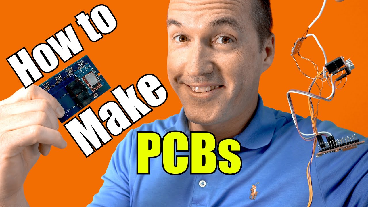
You’re about to embark on a journey to transform your simple DIY projects into professional-looking creations using custom PCBs. This video tutorial provides a straightforward approach to creating printed circuit boards, perfect for those who don’t fancy themselves as electrical engineers. You’ll learn how to handle non-conductive material, mount electrical components, and connect them with ease. The tutorial focuses on using EasyEDA, a user-friendly online tool, guiding you step-by-step through the entire process.
As you get started, you’ll explore two types of mounting components, surface mount and through-hole, with an emphasis on the beginner-friendly through-hole method. You’ll also get to grips with using a solder mask to keep solder confined to where it’s needed, making trace connections smoother. With the support of reliable manufacturers like PCBWay and handy tips on soldering, you’ll soon see your projects evolve into neat, professionally-finished boards. Get ready to dive in and share your PCB accomplishments with fellow enthusiasts!
Create your DIY projects into custom printed circuit boards (PCBs) with PCBWay (https://www.PCBWay.com) through this start-to-finish tutorial. Use Promo Code “TheHookUpWithPCBWay” for $5 off any order over $10.
Blinds Project Video: • Motorize and Automate your Blinds for…
EasyEDA Project: https://easyeda.com/smarthomehookup/v…
Github Project with User Submitted Boards: https://github.com/thehookup/Motorize…
Visit your website: http://www.TheSmartHomeHookUp.com
Follow you on Twitter: @TheHookUp1
Join you on Facebook: https://www.facebook.com/groups/47381…
Support your channel:
Patreon: / thehookup
Music by www.BenSound.com
Understanding PCBs
Printed Circuit Boards, commonly known as PCBs, are essential elements in modern electronics. They are the backbone of most electronic devices, providing a platform where various components can be mounted and interconnected to perform their desired functions.
Definition of PCBs
At its core, a PCB is a board made from a non-conductive material that supports and connects various electronic components using conductive traces or pathways. These traces are typically made of copper and etched onto the surface of the board. PCBs can range from simple single-layer designs to complex multi-layer configurations that cater to intricate circuits found in advanced technology.
Importance in Electronic Projects
PCBs are crucial in electronic projects for several reasons. Firstly, they offer a compact way to integrate and organize electronic components, which enhances the usability and efficiency of the device. Unlike wired connections, which can be messy and prone to errors, PCBs provide a stable and clean platform facilitating easier troubleshooting and assembly. This structural advantage makes your projects not only look more professional but also more reliable.
Types of PCB Components Mounting
When you start working with PCBs, you’ll encounter two primary methods for mounting components on the board: Surface Mount Technology (SMT) and Through-Hole Technology.
Surface Mount Technology (SMT)
Surface Mount Technology involves placing components directly onto the surface of the PCB. Components used in SMT are typically smaller, allowing for greater component density and compact designs. SMT is ideal for high-volume production due to its efficiency in assembly. However, the precision required can present a challenge for beginners and may involve a steeper learning curve.
Through-Hole Technology
Through-Hole Technology involves inserting the leads of components into holes in the PCB, which are then soldered from the opposite side. This method provides strong mechanical bonds and is known for its durability, making it a favorite in prototypes and projects subjected to stress or movement. Its simplicity makes it an excellent starting point for beginners who are new to soldering and PCBs.
Comparison for Beginners
For beginners, Through-Hole Technology is often recommended due to its simplicity and lower requirement for precision. The components are easier to handle and the soldering process is more forgiving. In comparison, SMT offers more advanced and compact designs but might not be suitable for first-time PCB creators due to its demands on precision and dexterity.
Solder Mask and Its Purpose
Once you’ve decided on the component mounting method, understanding other PCB elements like the solder mask becomes essential.
Function of a Solder Mask
A solder mask is a thin protective layer placed over the copper traces on a PCB. Its primary function is to protect these traces from environmental damage and prevent solder from accidentally bridging connections during the soldering process. It is typically green but can come in various colors for aesthetic preferences.
Benefits for PCB Durability
The solder mask enhances PCB durability by shielding the board from oxidation and preventing short circuits. It provides thermal resistance, aiding in your board’s longevity and operational reliability. By confining solder to specific areas, it ensures a tidy assembly and robust electrical connections.

Single-Layer vs. Double-Layer PCBs
PCBs differ in complexity, often determined by the number of layers they possess.
Understanding Layers in PCBs
A single-layer PCB has components and copper traces on one side, making it cost-effective and easier to manufacture. Double-layer PCBs, on the other hand, have copper traces on both sides. This configuration is particularly beneficial for routing more complex circuits as it allows traces to cross paths by utilizing both sides of the board.
Advantages of Double-Layered Boards
Double-layer boards offer more flexibility in design and can accommodate more components without requiring additional space. They allow for reduced size and weight of the device, which is desirable for compact and portable gadgets. This flexibility can facilitate more advanced projects, making double-layered PCBs an attractive option for intermediate to advanced electronics enthusiasts.
Ground Planes and Their Role
In PCB design, ground planes play a crucial role in enhancing the board’s performance and longevity.
Electrical Noise Reduction
Ground planes act as a reference voltage level for components and help reduce electrical noise, which can interfere with the board’s function. By providing a large conductive area, they minimize inductance and ensure stable voltage levels across the board.
Heat Dissipation
Additionally, ground planes are effective in heat dissipation. By spreading out heat generated by components, they help in maintaining a consistent operational temperature, preventing overheating of key components.
Necessity for Beginners
For beginners, incorporating a ground plane in simple designs might be unnecessary. However, understanding and experimenting with them can be a valuable learning experience, offering insight into advanced PCB design considerations.
Getting Started with EasyEDA
To translate your PCB designs into reality, tools like EasyEDA simplify the design process.
Creating an Account
Starting with EasyEDA is straightforward. You’ll need to create an account on their platform. You can use your email or opt for a convenient login option like using your Google account, which saves time and streamlines the setup process.
Navigating the Interface
Once logged in, you’ll find the EasyEDA interface user-friendly, especially for beginners. The main dashboard offers quick access to start new projects, and a library of components is available to build your schematic. As you navigate, you’ll become familiar with the layout and tools, enabling you to create and modify designs with confidence.
Step-by-Step PCB Design Process
Creating a PCB involves a series of methodical steps which you can follow using EasyEDA.
Initiating a New Project
To begin, initiate a new project in EasyEDA. Name your project according to your goals. This organizational step ensures that you can easily locate and manage your projects as you work on them.
Placing Components
In schematic mode, you start by placing components on your board. EasyEDA’s extensive library allows you to search for and select components relevant to your project. This step is crucial for visualizing your circuit and planning the layout.
Connecting Components
Once components are placed, the next step is connecting them. You’ll draw wires between components to reflect their connections in your final design. Proper labeling aids in keeping track and ensuring that every connection aligns with your schematic.
Using the Auto-Router Feature
After placing and connecting components, utilize the auto-router feature for tracing paths on the board. This feature is invaluable for beginners as it automatically calculates the optimal path for each trace, reducing the risk of errors and optimizing board layout.
Generating Gerber Files
When your design is complete, conversion into Gerber files is necessary for PCB manufacturing.
Purpose of Gerber Files
Gerber files are a standard format used to describe the PCB design to manufacturers. They contain all the information required, including the layout, layer configuration, and design specifics, necessary to produce a physical board.
Steps to Generate in EasyEDA
In EasyEDA, generating Gerber files is a simple process. After finalizing your design, navigate to the export option and choose ‘Gerber.’ EasyEDA will compile the design details into Gerber format, which you can download and submit to your manufacturer.
Manufacturing with PCBWay
With Gerber files ready, manufacturing is the next phase.
Uploading Gerber Files
PCBWay is a well-recognized and reliable service for manufacturing PCBs. By creating an account on PCBWay, you can upload your Gerber files directly, specifying your design preferences and requirements for production.
Understanding Pricing and Service Benefits
PCBWay offers competitive pricing and various options that allow you to tailor your order according to budget and needs. They provide advanced services such as different finishes and material choices, which can add professional touches to your project.
Processing Your Order
After uploading your files, review the pricing details and service options before confirming your order. PCBWay ensures that the manufacturing process is efficient and hassle-free, with tracking available to keep you updated on your order status.
Conclusion
Creating a PCB from scratch involves understanding basic concepts, leveraging design tools like EasyEDA, and collaborating with manufacturers such as PCBWay. The process is remarkably accessible even to beginners, and with practice, you can craft professional-looking boards for your electronic projects. Embark on your PCB design journey and explore the endless possibilities DIY electronics has to offer. Remember, each project is an opportunity to learn and innovate, so embrace the challenges with enthusiasm!
