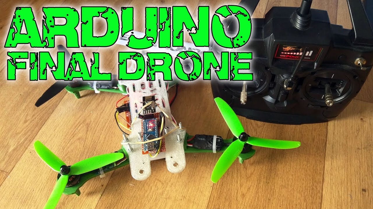
You’re about to embark on an exciting journey to build your very own Arduino-based drone. In this installment, you’ll discover how to assemble the drone by gathering all the components from previous tutorials. You’ve already explored constructing a flight controller and a radio receiver/transmitter in earlier segments. Now, it’s time to put everything together into one impressive flying machine.
You’ll learn about essential components like the 1804 brushless motors, electronic speed controllers, and a 3D printed body. Step-by-step guidance will ensure you’re able to configure motors and various connections properly to get your drone airborne. Whether you’re using 3D printed parts or opting for alternatives like balsa wood, this tutorial will set you on the path to flying success. Future videos will take a deeper look into customizing your flight controller, so stay tuned for even more drone-building adventures.

Sure, here’s the text rewritten according to your guidelines:
First of all, apologies for my accent on the word “ESC.” LOL
You will build a complete Arduino-based drone. This tutorial is split into several parts. In this video, you will assemble the drone using all the components from the previous two videos. You can access all the codes, schematics, and examples below. If you’re looking for more, stay tuned for upcoming videos where I explain how the PID works and how to develop your own code for the flight controller.
Support my projects on Patreon: /electronoobs
Your Q&A page: http://electronoobs.com/eng_preguntas…
Canal en Español: /electronoobs en español
Part 1: • Arduino drone – Part1 Flight Controller
Part 2: • Arduino drone – Part2 Transmitter & R…
—————–LINKS——————-
STL original source: https://www.thingiverse.com/thing:116…
Drone build webpage: http://www.electronoobs.com/eng_robot…
STL files: http://www.electronoobs.com/eng_robot…
Flight controller webpage: http://www.electronoobs.com/eng_robot…
Transmitter/receiver webpage: http://www.electronoobs.com/eng_robot…
Full tutorial webpage: http://www.electronoobs.com/eng_robot…
Price/Part list webpage: http://www.electronoobs.com/eng_robot…
——From previous videos——
NRF24 library: http://www.electronoobs.com/images/Ar…
Multiwii download: http://www.electronoobs.com/eng_robot…
Part list (photos): http://www.electronoobs.com/eng_robot…
http://www.electronoobs.com/eng_robot…
PID tutorial: http://www.electronoobs.com/eng_robot…
—————MATERIAL—————
LIPO battery: http://www.ebay.com/itm/T-Plug-11-1V-…
ESC 12A: http://www.ebay.com/itm/4-x-Emax-12A-…
1804 brushless motor: http://www.ebay.com/itm/4x-Brushless-…
5030 propellers: http://www.ebay.com/itm/8-pairs-Gemfa…
LIPO connectors: http://www.ebay.com/itm/10-Pairs-20pc…
Slide switch: http://www.ebay.com/itm/50-Pcs-2-Posi…
Flight controller: DIY
Radio receiver/transmitter: DIY
Drone body: DIY: http://www.electronoobs.com/eng_robot…
Or: http://www.ebay.com/itm/250mm-Mini-Mu…
—————SCHEMATICS———–
ESC calibrate: http://www.electronoobs.com/images/Ro…
Lipo connection: http://www.electronoobs.com/images/Ro…
Propeller spin direction: http://www.electronoobs.com/images/Ro…
——————–CODE——————
ESC calibrate: http://www.electronoobs.com/eng_robot…
——From previous videos——
Transmitter code: http://www.electronoobs.com/eng_robot…
Receiver code: http://www.electronoobs.com/eng_robot…
Receiver test: http://www.electronoobs.com/eng_robot…
Multiwii: http://www.electronoobs.com/eng_robot…
Make sure to like, share, and subscribe to encourage me. Thank you
Materials and Parts Required
To get started with building your Arduino-based drone, you’ll require a few essential materials and parts.
3D Printed Drone Body or Balsa Wood Alternative
You’ll need a frame for your drone. You can either 3D print the body using PLA material if you have access to a 3D printer. The STL files for printing can usually be found with online tutorials or communities. If a 3D printer isn’t available, balsa wood is a great lightweight alternative. Simply print out a layout, adhere it to the balsa wood, and carefully cut out each section. Drill holes where necessary to assemble your drone body.
Brushless Motors and Electronic Speed Controllers (ESC)
Brushless motors are key for drone flight, offering efficiency and power. For a 250-sized drone (where 250 indicates the diagonal distance in millimeters between motors), you might use motors like the 1804 size. The ESCs are needed to control these motors. Opt for 12-amp ESCs which are appropriate for controlling the power supply to each motor in the drone.
Flight Controller and Connectivity
The flight controller is essentially the brains of your drone. It’s the piece of hardware that manages your drone’s flight by processing sensory inputs and controlling the motors. You’ll integrate this with a radio receiver for remote communication. A DIY flight controller and receiver can be sufficient for this purpose.
Propellers, Battery, and Connectors
For a 250-class drone, 5030 triple-blade propellers are recommended. You’ll also need an 11.1-volt LiPo battery to power your drone. Ensure you have the right connectors, switches, and a soldering kit to connect everything together securely.
Miscellaneous Hardware and Tools
Other hardware includes 3mm screws, washers, zip-ties, and wires to secure and connect all the components. Basic tools such as a soldering iron, screwdrivers, and pliers will help in assembling the parts.
Configuring the Electronic Speed Controllers
Configuring your ESCs is an important step to ensure proper operation of the drone.
Understanding ESC Functionality
Electronic Speed Controllers are vital for translating the signals from the flight controller into actual motor speeds. Each motor is connected to an ESC, which, in turn, connects to the power battery and the flight controller.
Soldering and Wiring Connections
Begin by soldering the three wires from each ESC to your respective brushless motor. The middle wire of the ESC should be connected to the middle wire of the motor, ensuring initial compatibility. If your motor spins in the wrong direction later, you can simply swap these connections.
Setting Up PWM Range with Arduino
The ESC needs to be configured with the correct pulse width modulation (PWM) range, typically from 1000 to 2000. Using an Arduino board, you can set this range by writing a simple script that initializes the ESC into configuration mode.
Fine-tuning Motor Spinning Directions
Once motors are connected, you should confirm their spinning directions. Two should spin clockwise and the other two counterclockwise to maintain stability. If any motor spins incorrectly, swap the connections of the two outer wires of the ESC.
Assembly of the Drone Framework
With the electronics configured, you can now start assembling the drone frame.
Attaching Motors to the Frame
Carefully screw each motor onto the designated positions on your drone frame. Ensure they are placed firmly to avoid any balance issues during flight.
Mounting ESCs Securely
Use zip-ties or screws to firmly attach each ESC to the drone frame. Keeping them secure prevents any unwanted movement or detachment during flight.
Ensuring Structural Integrity
When connecting the arms of your drone to the main body, use 3mm screws to ensure they are tightly secured. This step ensures your drone stays intact, even after demanding flights.
Power Distribution Setup
To power your drone, you need to properly distribute the power from the battery to the ESCs and other components.
Wiring the Power from Battery to ESCs
All ESCs should connect to a central power distribution system that links to your battery. Solder connections should be firm and well-insulated to prevent any short circuits.
Adding a Switch and Connectors
For safety, include a switch between the battery and ESCs to cut power when necessary. Appropriate connectors, such as a male LiPo connector for the battery, will make it easier to swap batteries as needed.
Following the Power Schematics
Ensure your power setup follows a clear schematic, showing connections to each ESC and the flight controller. A precise schematic fosters easier troubleshooting and upgrades later.
Installing the Flight Controller
Next, you need to install and configure the flight controller.
Positioning and Fixing the Controller
Secure the flight controller in the center of your drone. Use double-sided tape or screws to fix it, ensuring that it’s level for accurate flight data reading.
Providing Power Supply to the Controller
One of your ESCs will supply power to the flight controller. Connect a 5V wire from your chosen ESC to provide consistent power.
Connecting ESCs to PWM Outputs
Connect each ESC to the designated PWM outputs on the flight controller. Remember to follow the schematic’s order; for example, digital pins might correspond to different motors.
Integrating the Radio Receiver
To control your drone remotely, integrate a radio receiver.
Connecting PPM Signal to Flight Controller
Connect the PPM signal from your radio receiver to the flight controller. This connection enables the flight controller to interpret commands from the remote transmitter.
Sharing Ground and Power
Ensure the radio receiver shares the same ground and power supply as the flight controller to ensure seamless communication and power distribution.
Securing the Radio Receiver
Secure the radio receiver to your drone’s frame, keeping antenna orientation in mind to maximize signal reception during flights.
Configuring the MultiWii Software
MultiWii software allows you to calibrate and configure your flight controller settings.
Installing MultiWii and Establishing Connection
Install the MultiWii software on your computer and connect your flight controller via USB. Establish a connection to start configuring your drone.
Calibrating Sensors and Setting Flight Modes
Use MultiWii to calibrate the drone’s accelerometer, ensuring the drone measures its orientation accurately. You can also set flight modes using auxiliary switches on your transmitter.
Ensuring Receiver and Transmitter Communication
Verify the receiver’s and transmitter’s operation by observing changes in throttle and directional controls within the MultiWii software.
Performing Flight Tests
You’re now ready to test your drone in action.
Powering Up and Initial Motor Spins
Turn on your drone and do a check of all systems. Initially spin the motors without propellers to ensure they respond correctly to commands.
Adjusting Throttle and Maneuverability
Perform gradual throttle increases and check for smooth motor operations and proper orientation controls.
Ensuring Proper Flight Dynamics
During initial flight tests, check that your drone maintains balance and reacts correctly to throttle, yaw, pitch, and roll adjustments.
Fine-tuning and Troubleshooting
Post-flight, fine-tuning might be necessary to optimize performance.
Adjusting PID Values for Stability
Using the MultiWii interface, adjust PID values to fine-tune how your drone stabilizes itself during flight, ensuring it reacts appropriately and predictably.
Recognizing Common Flight Issues
Watch closely for common problems like excessive vibrations, drifting, or sluggish responses. Each might indicate issues with motor balance or PID tuning.
Improving Flight Performance and Response
Iteratively tweak settings and consider adding vibration damping materials or tightening structural components to improve overall flight performance.
Conclusion
Summary of the Build Process
You’ve assembled your very own Arduino-based drone from scratch, involving several steps from securing the frame to setting up complex electronics.
Future Enhancements and Projects
This project is just a starting point. You can explore adding features like GPS, cameras, or enhanced flight modes.
Encouraging Development and Learning
Building a drone offers an engaging experience in electronics and programming. Continue experimenting and learning to further advance your skills and knowledge. Happy flying!
