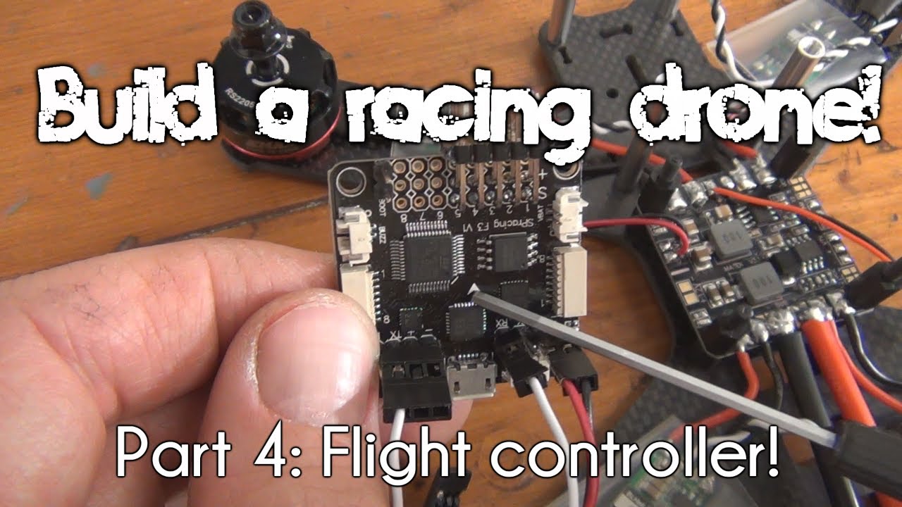
You’re on an exciting journey to master the art of building a racing drone, and this part of the series zeroes in on installing the flight controller, the sophisticated “brain” of your quadcopter. With clarity and precision, this guide illuminates each step in the installation process, starting with understanding the layout and connection of the flight controller to its components. By the end of this article, you’ll know how to diagram the layout, solder pin headers, and install all essential cabling, even diving into the nuances of combination Power Distribution Board (PDB) and Flight Controller (FC) units.
The video offers a detailed look at wire management and connection types such as power, PWM, and UART, ensuring you can power up and communicate effectively with various components. With practical tips on using servo extension wires and the order of execution for tasks like soldering, you’re equipped to handle each technical aspect confidently. This resource prepares you to move on to the next exciting phase: installing the FPV system, with everything firmly in place and functioning as intended.
In this series, you discover everything essential for constructing a racing drone! This part demonstrates the installation of the flight controller! Observe how you diagram your layout, solder on pin headers, and set up all the cabling!
This version is updated to include PDB+FC combinations and various wiring styles.
You can read the text article here: http://www.propwashed.com/drone-build…
Other articles mentioned:
Flight Controller Buyers Guide: http://www.propwashed.com/flight-cont…
Learn to solder: http://www.propwashed.com/soldering-101/
Part 5 Video: How to build a racing drone | Part 5:…
You can follow us and read more at:
/ propwashed
/ propwashedsite
Understanding the Flight Controller
A flight controller is a crucial component of a racing drone, functioning as its brain by managing communication, stabilization, and control. As the nucleus of your drone’s electronics, it receives signals from the pilot’s transmitter and then sends commands to the ESCs (Electronic Speed Controllers) to adjust the motors’ speed. You’re essentially transforming your manual flight commands into automated responses that keep your drone in the air and on its intended path.
Function and Role in a Racing Drone
The flight controller is responsible for interpreting input from the user and sensors to ensure stable flight dynamics. It processes signals from your remote control and translates those into throttle, roll, pitch, and yaw movements. Alongside regulating motion, it stabilizes the drone in various flight modes, be it steady hovering, rapid acceleration, or sharp cornering. The brain comparison is apt because it also allows for advanced modes like flips and rolls, which are necessary for competitive racing.
Customization Options
The customization potential of a flight controller is vast. By connecting it to a PC and using specialized software, you can adjust the parameters such as PID settings for tweaking how the drone reacts to inputs or a change in environmental conditions. You might also access settings for modes, enhance flight stability, or set up safety protocols. These customization capabilities allow your drone to perform optimally under different racing conditions, essentially tailoring the drone’s performance to your flying style.
Common Flight Controllers Used
In the realm of racing drones, some flight controllers have stood the test of time for their performance and reliability. The SP Racing F3, for example, is a favored choice due to its adaptability and beginner-friendly design. Other popular choices include the Betaflight and Cleanflight-compatible boards, which provide a range of settings tailored to various types of flying from acrobatic to cinematic.
Preparing for Installation
Before diving into the technical aspects, preparing thoroughly for the installation of the flight controller is critical. This phase involves gathering the right tools and understanding the specs of the flight controller you’re about to install.
Tools and Equipment Needed
For a smooth installation process, you’ll need various tools such as a soldering iron, solder wire, soldering flux, wire cutters, and tweezers. Additionally, having heat shrink, a heat gun, and a multimeter can be incredibly beneficial for ensuring clean connections and verifying proper electrical flow. These tools will aid in connecting components securely, ensuring the longevity and reliability of your system.
Safety Precautions
Safety is paramount when working with electronics. Make sure you have an organized workspace with adequate ventilation to avoid inhaling solder fumes. Always wear safety goggles to protect your eyes from solder splashes and debris. Handling soldering irons with care is crucial to prevent burns or accidental damage to your components.
Reviewing the Flight Controller Specifications
Understanding your flight controller’s specifications beforehand is crucial, especially if you’re working with a combination PDB and FC unit. You’ll need to review power requirements, UART port allocations, and compatibility with your ESCs and other components. This knowledge will help you avoid damaging delicate parts and ensure everything works harmoniously once powered.
Diagramming the Layout
A clear and well-thought-out layout diagram simplifies the assembly process significantly. It acts as your blueprint, ensuring everything is connected in the right place.
Mapping the Flight Controller Connections
Before installation, outline which sockets and pins your components will occupy on the flight controller. This includes identifying ports for power, PWM signal, and UART connections. Mapping this out on paper (or a digital note) prevents confusion during assembly and helps you foresee any potential problems with wire routing or component placement.
Identifying Key Components and Their Positions
Knowing where each component fits into your drone framework is essential. Determine the positions of vital parts such as the ESCs, receiver, battery, and peripherals like GPS or telemetry devices. This foresight will help avoid cramped wiring and ensure efficient spacing.
Considering PDB and FC Combinations in the Planning Process
When using a combination PDB and FC unit, plan how the power distribution board will interact with the flight controller. Combined units can streamline your build but might require different wiring and mounting techniques. Carefully consider how wires will route between the two, keeping the layout clean and accessible.

Soldering Pin Headers
Next, you’ll need to solder pin headers to create connection points for your components. This step is critical for ensuring reliable connections.
Choosing the Right Pin Headers
When selecting pin headers, ensure they match the configuration needed for your flight controller. Typically, you’ll use straight pin headers for components like UART connections and 90-degree headers for ESC connections where space may be limited. The choice often depends on your frame design and available space.
Step-by-Step Soldering Guide
-
Preparation: Cut the pin headers to the desired length, matching them to the sockets on your flight controller.
-
Positioning: Insert the short end of the pin headers into the flight controller’s sockets. Use Helping Hands or other supports to maintain steady positioning.
-
Soldering: Heat your soldering iron and apply solder carefully to each pin, ensuring a solid connection to the board without creating solder bridges.
-
Inspection: Check all soldered joints to confirm they’re shiny and well-formed, indicating a good connection.
Common Mistakes and How to Avoid Them
A common soldering mistake is overheating the board, which can damage traces or pads. Keep soldering time minimal and apply heat only where needed. Additionally, avoid applying too much solder, which can cause bridging between adjacent pins.
Installing Cabling
With the pin headers in place, it’s time to connect your components using appropriate cabling techniques.
Using Servo Extension Wires
Servo extension wires simplify connections by providing color-coded wires for power, ground, and signal. These pre-assembled wires reduce construction time and minimize potential wiring errors.
Customizing Wire Lengths
Ensuring wires are the correct length prevents clutter and reduces potential interference. Trim wires to the necessary length, allowing a little slack for adjustments, but avoiding excess that could tangle or obstruct other components.
Connecting Signal and Power Wires
Begin by connecting power and ground wires from your power source to the flight controller. Then, connect signal wires from the flight controller to the ESCs, ensuring each wire matches correctly to its port as mapped in your layout.
Wiring Styles for Combination PDB and FC Units
For combination PDB and FC units, particular wiring styles optimize space and efficiency.
Types of Wiring Styles
There are linear and parallel wiring styles, among others, that influence cable management. Linear wiring follows straight paths and is often easier to manage, while parallel wiring may allow tighter setups in constrained spaces.
Advantages of Using Combined Units
The primary advantage is reduced weight and space savings. By having fewer separate components to mount, the overall structure becomes more streamlined. Additionally, combined units often simplify connections and reduce the amount of soldering and cabling required.
Specifics of Routing and Connecting Wires
When routing wires in combined units, consider the direct pathways that minimize crossing and interference. Use the shortest practical paths and secure cables with ties or clips to keep them out of propellers and mechanically secure.
Connecting the Components
With wiring in place, it’s time to connect each component to the flight controller.
Power Connections: Power and Ground Wires
Ensuring proper power distribution is critical. Connect power and ground wires to the designated pads on the flight controller, paying attention to polarity to avoid damage. These connections will typically come from the PDB.
PWM Connections and Communications with ESCs
Connect each ESC to the flight controller using a signal wire and a matching ground wire. Ensure that the signal wire aligns with the correct pinout for effective communication, as this enables the flight controller to control each motor’s speed.
Using UART Ports for Peripheral Connections
Connect additional peripherals like receivers, telemetry devices, or OSD modules using the flight controller’s UART ports. Be sure to connect the RX and TX correctly, as this allows proper data exchange between devices and the flight controller.
Mounting the Flight Controller
Finally, you will mount the flight controller securely within the drone frame.
Ensuring Proper Fit and Placement
Place the flight controller onto the frame standoffs. It should align with the drone frame’s designated mounting holes and any directional indicators (like arrows) should point forward.
Securing Components to Avoid Movement
Use screws or other mounting hardware to fasten the flight controller. Rubber or silicone spacers may be employed to reduce vibrations that could interfere with sensitive electronics.
Checking Alignment with the Drone Frame
Once secured, re-check that the flight controller is aligned with the drone’s frame to ensure that all connected parts remain tension-free and any weight distribution is properly balanced.
Wire Management and Cleanup
Good wire management not only contributes to a professional look but also minimizes in-flight mechanical failures.
Tidy Routing Techniques
Group and route wires together using ties, keeping them aligned along the frame. This neaten process avoids overlaps that could interfere with drone operations or maintenance.
Securing Loose Wires
Secure any remaining loose wires using zip ties or tape. Ensure wires are bundled away from propellers and other moving parts to prevent wear or damage.
Dealing with Leftover Components
Any components not needed should be carefully stored for future use or upgrades. Keeping spare parts can be useful for on-the-fly repairs or re-configurations.
Conclusion
Recap of Key Installation Steps
You’ve learned how to map the layout, solder pin headers, install cabling, and connect all components efficiently. Each of these steps was designed to ensure a steady performance and clean installation process.
Importance of Precision and Care
Throughout each stage, precision and a careful approach ensure your drone operates safely and efficiently. Missteps in soldering, wiring, or mounting can lead to malfunctions, requiring more time for troubleshooting and repairs.
Next Steps: FPV System Installation
With the flight controller installed, it’s time to focus on integrating the FPV (First Person View) system, the next critical component of your racing drone. Stay tuned as we continue our series, taking your drone from a flight-ready shell to a fully immersive flying experience!
